CLIFF NOTES
The information provided in this section is open to comments, corrections, additions and any other information that may be of interest to collectors.
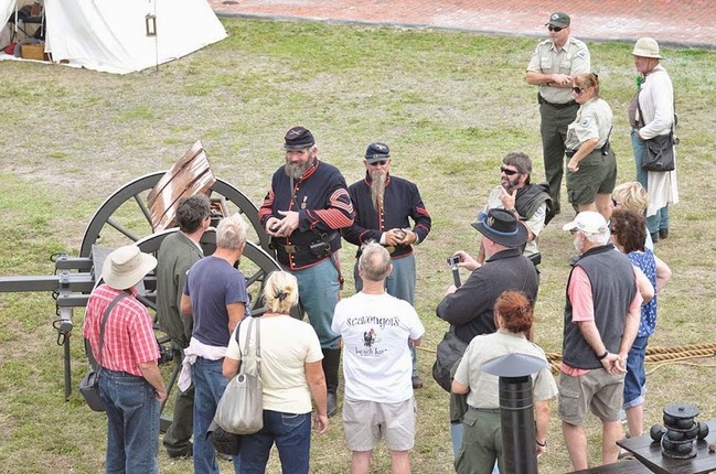
Teaching the park visitors about muzzle loaded artillery at Ft Zachary Taylor, Key West, Florida. 2/15
I. Painting and Lettering Projectiles
Most projectiles sought by collectors are found with most if not all the paint and the lettering worn or weathered away. Sometimes the projectile is rusted and even pitted. Many choose to restore these projectiles to their original condition. Repainting and lettering although time consuming, is relatively simple.
Back in the day one could purchase rub on transfer lettering. Yellow for HE, Black for Illumination and early yellow projectiles and white for AP. They were relatively inexpensive, could be found with the correct colors and sizes and were very easy to use. Unfortunately, now they are very difficult to find in the proper style and colors.* The solution is peel and stick letters. Available in many sizes and styles from any art supply or hobby store., it's not important what color they are since you'll be painting over them.
1. If your projectile is heavly pitted it can be restored with automotive body putty. Be sure to be aware of any stamping on the projectile body and avoid covering. Smooth and sand the projectile as necessary and prime. Remember, projectiles do not have a perfectly smooth surface. Indeed turning marks are usually present.
2 Using the desired color for the lettering, spray the area lightly just enough to cover. Allow to dry for 24 hours minimum.
3. Carefully apply peel and stick letters using moderate pressure.
4. Paint the projectile the proper color and allow to dry for about a half an hour or so. Do not saturate surface. Two very light coats are better.
5. Use a pin or the tip of your pocketknife to carefully peel away letters.
6. When paint is completely dry and hard, sometimes as much as a week, you can lightly sand any uneven edges of the letters and apply one or two coats of flat clear lacquer. (Available at art supply stores.)
* Any suggestions where correct rub on transfer decals are available, please post.
This method can be used for other restorations such as vehicle lettering, ammo cans, etc. Your comments are welcome!
II. Projectile Classification
A complete round of artillery ammunition, with the exception of blank ammunition, always consists of 4 parts: the case, the projectile, the propellant and the primer. The propellant can either be black or smokeless powder in the form of cylindrical grains of various sizes, in flakes or in long hollow tubes (cordite). This propellant is packed into a case or into a combustible bag (powder bag). Depending on how the propellent is loaded into the gun with the projectile, artillery ammunition is classified into four groups:
Fixed Ammunition
A fixed round of artillery ammunition has a shell casing that is crimped or "fixed" to the projectile. The shell casing contains the propellant (powder) and the primer.
Semi-Fixed Ammunition
With semi-fixed ammunition the casing and the powder charge still fit together but the projectile can be removed from the casing (in the field) to adjust the size of the powder charge. A good example of this is the 105mm howitzer round. At the direction of gunner, who consults the fireing table for ballistic reference, the projectile handler will remove the projectile from the casing and add or remove propellent "increment" bags as directed.
Separated Ammunition
With separated ammunition the shell casing is not attached to the projectile at all. Normally, the shell casing for separated ammunition is closed with a plug to protect the propellent and assist with pushing the projectile into the chamber of the gun. An excellent example of separated ammunition is the Naval 5"38cal. Gun casing. There is a great photograph of a 5" case in the projectile section of this site (#25) as welll as a projectile (#87).
Separate Loading Ammunition
Fixed, Semi-fixed and Separated ammunition contains the primer. Separate loading ammunition consists of three parts: the projectile, the powder case or bag and the primer. Although this classification of loading is usually encountered in large calibers, (155mm, 175mm etc) a great example is the muzzle loaded rifled cannons of the American Civil War. The pre-measured powder was contained in a separate linen bag and rammed down the barrel first. Then followed by the projectile (sometimes together). A separate "friction" primer was then inserted into the vent and a lanyard attached to fire the gun. It is interesting to note that even with such an involved loading procedure, a good highly trained gun crew could fire 2-3 shots per minute. (Although this was highly dangerous given the chance of a premature discharge that would result in serious and sometimes fatal results to the person ramming the live charge-projectile home)
Restoring Or Replacing Projectile Rotating Bands.
Some projectiles are received by the collector in fired condition. The rifling from the barrel etches the rotating band to insure it spins to maintain stability. With some projectiles the collector may find this interesting when explaining how rifling works. However, for those collectors who prefer the projectile look as made, part one of this section will provide valuble help explaining a tried and proven way for a correct and lasting restoration. Also, some projectiles may be received with the rotating band missing entirely. Part two will suggest and instruct a proven way to replace them.
*Please note that you must have a lathe to accomplish these projects.*
Part One
I. Preparing the projectile
a. Chuck the projectile in the lathe base first and center. Finding exact center of the projectile nose may require fabricating an insert of some kind that will screw into or be able to be secured in the fuze hole. Drill center as necessary and be sure that nose of projectile runs as true as possible. Re-adjust as necessary.
b. Carefully cut away the rifling engraved rotating band down even with the projectile body. Remove the last few thousandth's with a flat file if necessary. It is extremely important that this is perfectly flush and smooth.
II. Fabricating the rotating band and preparing for a shrink fit.
a. Choose the proper material. Brass, bronze or copper and turn the inside diameter a few thousandths smaller than the diameter of the turned down rotating band. Rough in the outside dimentions of the band.
b. Place the projectile securely in a vice taking care to protect the projectile body.
c. Find or fabricate from steel a sleeve that just barely but easily slides over the projectile body. This will be used to set the new band. Do not use aluminum as it is too heat sensitive.
III. Installation of new rotating band.
a. Preheat the shell slightly. It should be very warm to the touch. It cannot be cold. (if the projectile is completely cold, the new rotating band may cool and shrink too quickly and become stuck before reaching the desired position)
b. Holding band with a pliers heat red hot and quickly place on base of projectile. Drive it down into place with the pre-fabricated sleeve. and cool quickly with wet rag. When cooled, rotating band should be very tight.
c. Re-chuck in lathe being sure that projectile runs true and turn the correct dimensions of band. If band is loose it can be sweat soldered in place by once again pre-heating the projectile this time hot and sweating the band in place. However, this is rarely necessary.
Part Two
I. Note: To replace a rotating band that is completely missing the groove in the shell for the rotating band must be filled then machined to the same diameter as the shell. This is most easily accomplished using lead or zinc.
a. Fashion a light gauge strip of sheet metal that extends at least one inch above and below rotating band cavity and roll (by hand if necessary) around body being sure that it overlaps about an inch.
b. Tightly duck tape metal to body along sheet metal edges and across overlap.
c. Drill as large a hole as possible in sheet metal and pour as hot as possible lead or zinc until overflowing.
d. Wait about 15 seconds and remove sheet metal.
e. Note that the lead my be honeycombed and the process may need to be repeated. Small voids can be filled without the sheet metal by carefully pouring molten lead into voids with shell horizontal.
f. After cooling any areas of lead that protrude above the surface plane of the shell can be turned or filed as necessary.
g. Install new rotating band as per instructions in Part One/number III.
III. Interesting Notes.
The US model 1892 rifle (AKA Krag) began production in 1894. Many changes were made through a production period that ended in 1903 with at least 5 basic model changes. A few of these changes and comments are obscure and very interesting. For example: Often, an author will include a photo or comment about the item he was describing and although dubious at best, becomes accepted as fact. A great example of this is the US Springfield model "1808" flintlock musket - Attempting to easily identify the changes made to the US Springfield model 1795 that occurred about 1808, collectors designated and named this the model the 1808. This is a myth. The fact is, these changes were officially noted as the US Springfield model 1795 type II. However, somehow a description and photo of this weapon made it into a book of US military small Arms and has hence been accepted as fact.
The Headless Cocking Piece:
Another example of a random photo or mention in a book is the reference to the headless cocking piece being correct only on the Krag model 1899 carbines. The cocking piece on the 99 carbine (AKA headless cocking piece) was originally manufactured for the 1898 rifle. The change from the standard cocking piece was supposed to speed up manufacturing time by eliminating a machining step. However, after production began it was found that the new design was actually slower and production reverted to the old design. James E. Hicks in his early book of firearms "US Military Firearms" illustrates a 99 carbine with the headless cocking piece. As with the erroneous 1808 musket (actually a 1795 type III), once it was in a book it became accepted as correct. Unfortunately, it is not.
The Model 1899 Carbine sling: In the book "The Krag Rifle Story" (Franklin B. Mallory) the author explains that in 1900 a small number of model 1899 carbines were modified to accept slings for use by Engineer Units. To this end the Ordnance Department provided a small number of modification "kits" that included a rifle lower band with sling swivel, a stock swivel with two screws and an inletting pattern for positioning the lower swivel. Also provided were inletting wood chisels and a special sling. The cocking piece on the 99 carbine (AKA headless cocking piece) was originally manufactured for the 1898 rifle. The change from the standard cocking piece was supposed to speed up manufacturing time by eliminating a machining step. However, after production began it was found that the new design was actually slower and production reverted to the old design. James E. Hicks in his early book of firearms "US Military Firearms" illustrates a 99 carbine with the headless cocking piece. As with the erroneous 1808 musket (actually a 1795 type III), once it was in a book it became accepted as correct. Unfortunately, it is not.
The mystery of pulling the trigger with the middle finger:
The P17 rifle:
6pdr firing table:
.45 "Long Colt"
Shrapnel
What is the difference between artillery shrapnel and shell fragments?
Shrapnel, is "an artillery projectile provided with a bursting charge, and filled with lead or metal balls, exploded in flight by a time fuze." It was named for its inventor, General Henry Shrapnel of the British Army, who died in l842.
Pryor to WWII, shrapnel was regarded as the most efficient type of ammunition against troops in the open. The 75mm shrapnel projectile contained 270 lead balls, each about a half-inch in diameter, in a smoke-producing matrix. The 155mm shrapnel packed a lethal load of 800 balls*. Each projectile was practically a flying shotgun which was fired, by means of the time fuze, ideally at the height which would produce the maximum effect on the enemy. At the moment of burst, the bullets shot forward with increased velocity, normally without fracturing the case. The result was a cone of bullets which swept an area generally much larger than the area made dangerous by the burst of a high explosive shell of the same caliber. Even for the relatively small 75mm gun, the effective area at a range of 4,000 yards was about 35 yards wide and 50 yards long. In addition, some balls with equally effective velocity were scattered less densely over a zone roughly twice as wide and several times as long. The height of burst had to be adjusted by observation of the smoke puff produced at the moment of explosion, and by proper changes in the setting of the time fuze.
It was not very effective in trench warfare of the World War I type, and that fact influenced the decision to abandon it. But shrapnel was abandoned primarily because it was difficult to get the height of burst adjusted properly even under conditions of good visibility, and impossible to do this in darkness or bad weather. It also added to the complications of ammunition manufacture and supply. With the proximity fuzes now available the problem of adjustment of the height of burst could be overcome; the need for a smoke producing matrix to permit observation of height of burst would be eliminated; and sharp hard-metal missiles, not unlike small shell fragments, might replace the round lead balls. The complication of ammunition supply would remain as an objection.
Fragments are the shards, fractured pieces and collateral debris that are the result of an explosion from an artillery projectile.
* 155mm Shrapnel Shell
There is a photograph of this projectile in the projectile section of this site. Item #27
When purchased, 20 years ago, it had been fired and the rotating band was missing. The photograph shows it completly resored and a new rotating band in place.
When purchased, 20 years ago, it had been fired and the rotating band was missing. The photograph shows it completly resored and a new rotating band in place.
